

and the light house, which in the original device would be based on a halogen bulb of at least 15-20 Watts:

In my case this part was missing, so when I ordered the illuminator, I knew I had to figure out a solution later.
Just as with the regular transillumination system that is built into the microscope, filament illumination was mostly the state of the art back in the 1960's when these microscopes were produced.
But today with high brightness LEDs being obviously mainstream, there is no benefit in trying to preserve the original lighting system. As such I did that modification soon after I received my Olympus KHC microscope. You may see the detailed steps of this conversion in this page:
http://creationfactory.blogspot.com/2016/09/reconditioning-50-year-old-microscope_10.html
For the epi-illumination system, it made perfect sense to follow the same approach, which in this case coalesced with the need for building a light source from scratch for this vertical illuminator.
There are hardly any disadvantages in using LEDs for the illuminator: these draw less power for the same amount of visible light, can be somewhat more compact (heatsink size must be factored-in), and the light wavelength is consistent across the entire range of intensity control. This removes the need for adding a daylight filter to the light output. Also, there is very little radiant heat emitted, being less likely to disturb the certain types of specimens.
This light house would have to fit the vertical illuminator tube, the same way as the original part from Olympus. As I don't have any lathe or machining gear, I had to figure out which readily available metal tube of some sort would be adequate.
A trip to the chinese store, and found one of those basic aluminium LED flashlights with the dimensions (in particular the head part) that seemed appropriate. Not exactly this model but somewhat similar:
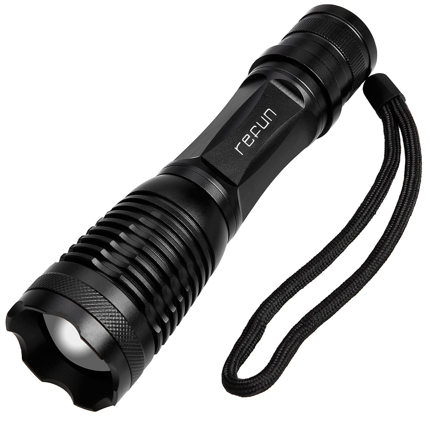
The idea would be to use the head (where the LED is housed) and scrap the rest.
The LED itself I didn't reuse. Instead I have ordered a few 10 Watt cool white LEDs:

This would theoretically give a greater power margin if required, and as it is composed of an array of discrete LEDs distributed of a substantial area, could potentially (with a proper diffuser) provide a more evenly distributed light across the area of the vertical illuminator light path.

In order to drive the LED I went for a basic constant current device that can easily be found on chinese suppliers online. It is based on an LM2596S step-down regulator chip:

This is the same model that I have used previously for the transillumination conversion.
I did a small adaptation to be able to control the light from a 1 K linear potentiometer. It consisted of: 1) set the voltage control trimmer pot to an optimal value; 2) use the current limiter trimmer to set the current limit for the LED operation; 3) add the new potentiometer in series with the voltage control trimmer. By adjusting it, the light output is varied between a near-off minimum, and the maximum within the limit set by the trimmer.
Was also able to find online in the same supplier, an extruded aluminium box with the adequate dimensions. In order to correctly place the LED driver board inside the aluminium enclosure, mounted the PCB over a perf-board PCB with the exact dimensions to slide within the rails of the enclosure and exactly fit inside:

The potentiometer was mounted to the side of the enclosure, for better accessibility during the operation:

One of the panels served to fit the LED assembly built based on the flashlight head:

The rear panel would house the DC connector and the power switch:

With everything mounted and soldered, it would be time to put it all together:

And at last, the finished product:


Attached it to the vertical illuminator, and went on testing it with a metallurgical specimen:

The result fell within the expectations, with a reasonably homogenous light obtained. A proper diffuser is still to be added to the light path. The individual LEDs in the chip produce some brighter spots which are less perceivable depending on the position and adjustment of the light house.
The next step in the microscope improvements will be to replace the binocular head with a trinocular one.
I spent some time patiently looking for an adequate deal on ebay for the trinocular head that fits this microscope. The few auctions I found for this head in particular, had quite high asking prices. The only alternative I could find was a nearly complete Olympus CK inverted microscope featuring this head and its eyepieces:

Once it arrives, I will test the trinocular head, and attach to the SLR camera. With this head in place, photomicrography will be much more convenient to perform. Hopefully will post on that matter, once the microscope arrives.
No comments:
Post a Comment