

Thursday, July 1, 2010
Power pack!
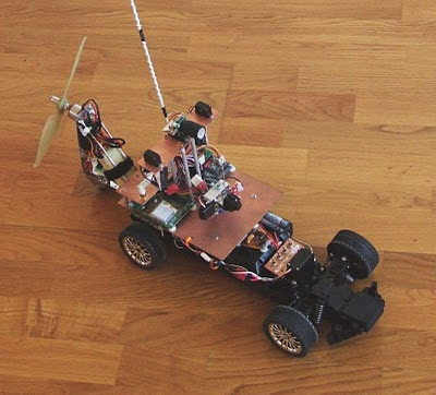
While the rear wheel traction motor provides plenty of power for normal operation, the curiosity of obtaining some extra power through a different propulsion method is appealing. Since I had some parts from a unfinished airplane project, the materialization of another exclusive idea became real: to build a special trailer for the car, with a single purpose - to push the car even faster, with the help of a propeller instead of traction wheels. Featuring a 9x6E propeller, a 150 Watt brushless motor, an 18 A ESC, and a 1300 mAh LiPo battery, this trailer provides the closest one can ever get from raw rocket power, with controller propulsion.
Wednesday, June 2, 2010
Sensors are never too many

While it is important to design a autonomous rover capable of performing even under the worst conditions and with the least available information from the surrounding environment, if we can provide good information, it will certainly lead to better results as long as we have a good software implementation behind it.
Tuesday, May 4, 2010
System override
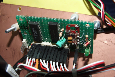
Unlike some other domains, with robot software bugs can have expensive outcomes. In order to avoid unpleasant mishaps, I have decided to implement a hardware solution for preventing software originated problems that could cause a calm, boring robot to become a runaway beast hitting hard against walls, people, animals and anything that is in its way. To achieve this I have built a PWM control source multiplexer:

Sunday, May 2, 2010
Almost autonomous
With all the hardware prepared (except the quadrature encoder on the wheels, which is still to be implemented and installed), all conditions were met in order to be able to write some code and make the car finally move on its own.
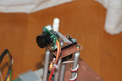
I have first added the sonar module (the previously mentioned SRF02). This implied making a small aluminium support to fixate the sonar to the servo, while still being able to slightly adjust the tilt:
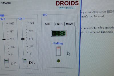
After installing it, made a quick check and read the ranging data directly through the MuIn original Windows application:
Every thing was fine. It was time to add more code to the MuIn PIC, implenting useful functions for the robot. A singe command returning both range data and the servo position would be useful, so I implemented it. It essentially consists of the following structure:
Each element is 8 bytes long. The PIC responds with the following answer format:
This allows a measurement to be taken, while the servo is sweeping.
A small video of the car in action:
I have first added the sonar module (the previously mentioned SRF02). This implied making a small aluminium support to fixate the sonar to the servo, while still being able to slightly adjust the tilt:

After installing it, made a quick check and read the ranging data directly through the MuIn original Windows application:

Every thing was fine. It was time to add more code to the MuIn PIC, implenting useful functions for the robot. A singe command returning both range data and the servo position would be useful, so I implemented it. It essentially consists of the following structure:
| '@' | 'F' | 'S' | I2C addr | servo nr | 0 | 0 | '#' |
Each element is 8 bytes long. The PIC responds with the following answer format:
| '@' | 'F' | 'S' | I2C addr | servo nr | Range HB | Range LB | Servo HB | Servo LB | '#' | Checksum |
This allows a measurement to be taken, while the servo is sweeping.
A small video of the car in action:
Sunday, April 25, 2010
More stuff on the pipe
The good work goes on, and the objective of achieving a fully autonomous rover is closing in. In this article I present 3 hardware additions:
First I found that the 1300 mAh LiPo battery could not be enough for long endurance roving activities. So I decided to add a pack of 4 NiMh AA batteries (2500 mAh each) dedicated to the Fonera. With this extra power, control and communications autonomy is guaranteed even if the powertrain pack becomes depleted. Additionally the efficiency is improved, because considering the fonera input voltage (5 V), and the voltage of the main pack (11.1 V), a regulator would be necessary, to properly drop the voltage. A linear regulator would not be a very efficient solution, and a switching regulator, in spite of being more efficient, is more complex and expensive. So with this separate pack, which provides around 4.8 V when fully charged, is enough for the Fonera (in fact the Fonera can be powered to a minimum of 3.5 V thanks to its internal low dropout regulator).

Thursday, March 25, 2010
Cognition on Wheels

Last, but absolutely not the least, is adding intelligence to the beast. Considering the budget constraints and simplicity of integration I decided by using a Fonera 2100 router as the workhorse for processing data. Equipped with a single chip Atheros solution, the integrated 32-bit MIPS R4000-class processor runs at 183.5 MHz, and is tipically enough for most network processing that is required. Additionally the IEEE 802.11b / 802.11g WiFi interface provides the means for remote communication with the vehicle. For local communication it features both an Ethernet interface, and a 3.3 V serial port.
Thursday, March 11, 2010
Let there be light!
One of the most pleasant situations is when can execute an idea without using any of your budget. It occured to me that having some onboard lightsource could be useful for the car, specially if you plan on doing night driving. Well I took a look at my repository of electronic junk, and found a pcb with 9 white leds from a broken flashlight, and a bunch of broken 9g microservos.
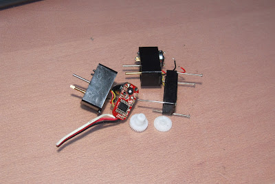
So I thought, well...if I could get the leds to be turned on and off through a free channel on my radio, it would be sweet.. And then took a look at one of the servos, and thought: I remove the motor, replace the encoder pot with a set of resistors, connect the leds in series with a small value resistor, and it should do the trick.
And so I did it: first analysed the servo operation in its original form. Connected the motor to an oscilloscope, and verified that a PWM signal that varies in duty cycle is fed to the motor. The further you move the stick, the more the duty cycle approaches 100%. Without surprise the peak voltage would be 5 V at the motor terminals (the same voltage that powers the servo).
Measured the pot resistance, which was 2 KOhm. Measured the current consumed by the leds while being fed with 3.1 V (minimum voltage for enough luminosity). It would draw 60 mA.
Then all I had to do was applying Ohm's law to find the appropriate resistor to drop the voltage, given the current that we know the LEDs consume. Found that the ideal value was 52 Ohms (V=RI <=> R = V/I <=> R = 3.1 / 0.060 = 51.66 ~ 52 Ohms).
I did't had this value (the closest resistor is 51 Ohms), so I used the closest resistor I could find at hand. Found a 47 Ohm, which in spite of being slightly smaller, it shouldn't harm the leds as I was being conservative with the voltage in the first place (these were being used in a flashlight powered by 3 AAA batteries - meaning that the voltage could be up to 4.5 V). The typical voltage to which white LEDs are rated is 4 volts.
With a bit of experimentation found an appropriate value for the resistors replacing the pot. One 2 K resistor between pin 1 and pin 3 of the pot terminal, and a 1 K resistor between pin 1 and pin 2.
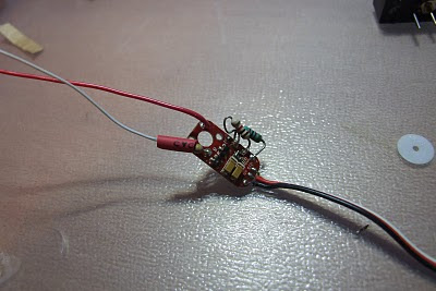
By doing this I trick the servo controller into thinking that the motor is always in the same position, while the user commands it to go to a different position. This causes the controller to continuously provide current to the motor, in an attempt to reach the desired position. Here instead of the motor we put the LEDs. The result is the LEDs being constantly lit while the stick is in a given region, and off in the remaining positions (because a negative voltage is fed to the LEDs - if a motor would be present instead, it would cause it to move in a different direction).
A little bit of soldering, and it was done! This way I had the cheapest possible RC headlight without spending a single cent.
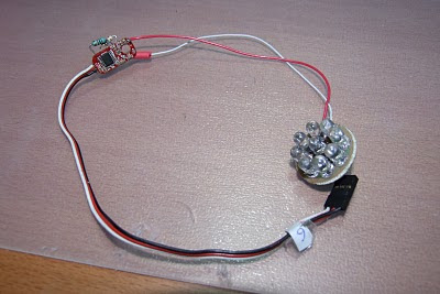
And finally, after putting heatshrink around the PCB, the work was done:

Subscribe to:
Posts (Atom)